Bass-treble tone control circuit


The LM1036 is a DC controlled tone (bass/treble), volume and balance circuit for stereo applications in car radio, TV and audio systems. An additional control input allows loudness compensation to be simply effected. Four control inputs provide control of the bass, treble, balance and volume functions through application of DC voltages from a remote control system or, alternatively, from four potentiometers which may be biased from a zener regulated supply provided on the circuit. Each tone response is defined by a single capacitor chosen to give the desired characteristic.
Features:
  • Wide supply voltage range, 9V to 16V
  • Large volume control range, 75 dB typical
  • Tone control, 15 dB typical
  • Channel separation, 75 dB typical
  • Low distortion, 0.06% typical for an input level of 0.3 Vrms
  • High signal to noise, 80 dB typical for an input level of 0.3 Vrms
  • Few external components required
Note: Vcc can be anything between 9V to 16V and the output capacitors are 10uF/25V electrolytic.

Audio Light Modulator


Audio light modulations add to the enjoyment of music during functions organised at home or outdoors. Presented here is one such simple circuit in which light is modulated using a small fraction of the audio output from the speaker terminals of the audio amplifier. The output from the speaker terminals of audio amplifier is connected to a transformer (output transformer used in transistor radios) through a non-polarised capacitor. The use of transformer is essential for isolating the audio source from the circuit in The sensitivity control potentiometer VR1 provided in the input to transistor T1 may be adjusted to ensure that conduction takes place only after the AF exceeds certain amplitude. This control has to be adjusted as per audio source level. The audio signal Proper earthing of the circuit is quite essential. The diode bridge provides pulsating DC output and acts as a guard circuit between the mains input and pulsating DC output. Extreme care is necessary to avoid any electric shock

5 band graphic equalizer using a single IC/chip


This circuit uses a single chip, IC BA3812L for realizing a 5 band graphic equalizer for use in hi-fi audio systems.The BA3812L is a five-point graphic equalizer that has all the required functions integrated onto one IC. The IC is comprised of the five tone control circuits and input and output buffer amplifiers. The BA3812L features low distortion, low noise, and wide dynamic range, and is an ideal choice for Hi-Fi stereo applica-tions. It also has a wide operating voltage range (3.5V to 16V), which means that it can be adapted for use with most types of stereo equipment. 

The five center frequencies are independently set using external capacitors, and as the output stage buffer amplifier and tone control section are independent circuits, fine control over a part of the frequency bandwidth is possible, By using two BA3812Ls, it is possible to construct a 10-point graphic equalizer. The amount of boost and cut can be set by external components.

The recommended power supply is 8V, but the circuit should work for a supply of 9V also. The maximum voltage limit is 16V.
The circuit given in the diagram operates around the five frequency bands:
  • 100Hz
  • 300Hz
  • 1kHz
  • 3kHz
  • 10kHz

Digital Volume Control


This circuit could be used for replacing your manual volume control in a stereo amplifier. In this circuit, push-to-on switch S1 controls the forward (volume increase) operation of both channels while a similar switch S2 controls reverse (volume decrease) operation of both channels.
A readily available IC from Dallas semiconductor, DS1669 is used here.

FEATURES:
  • Replaces mechanical variable resistors
  • Electronic interface provided for digital as well as manual control
  • Wide differential input voltage range between 4.5 and 8 volts
  • Wiper position is maintained in the absence of power
  • Low-cost alternative to mechanical controls
  • Applications include volume, tone, contrast,brightness, and dimmer control
The circuit is extremely simple and compact requiring very few external components.
The power supply can vary from 4.5V to 8V.

Ultrasonic Switch


Circuit of a new type of remote control switch is described here. This circuit functions with inaudible (ultrasonic) sound. Sound of frequency up to 20 kHz is audible to human beings. The sound of frequency above 20 kHz is called ultrasonic sound. The circuit described generates (transmits) ultrasonic sound of frequency between 40 and 50 kHz. As with any other remote control system this cirucit too comprises a mini transmitter and a receiver circuit. Transmitter generates ultrasonic sound and the receiver senses ultrasonic sound from the transmitter and switches on a relay. The ultrasonic transmitter uses a 555 based astable multivibrator. It oscillates at a frequency of 40-50 kHz. An ultrasonic transmitter transducer is used here to transmit ultrasonic sound very effectively. The transmitter is powered from a 9-volt PP3 single cell. The ultrasonic receiver circuit uses an ultrasonic receiver transducer to sense ultrasonic signals. It also uses a two-stage amplifier, a rectifier stage, and an operational amplifier in inverting mode. Output of op-amp is connected to a relay through a complimentary relay driver stage. A 9-volt battery eliminator can be used for receiver circuit, if required. When switch S1 of transmitter is pressed, it generates ultrasonic sound. The sound is received by ultrasonic receiver transducer. It converts it to electrical variations of the same frequency. These signals are amplified by transistors T3 and T4. The amplified signals are then rectified and filtered. The filtered DC voltage is given to inverting pin of op-amp IC2. The non- inverting pin of IC2 is connected to a variable DC voltage via preset VR2 which determines the threshold value of ultrasonic signal received by receiver for operation of relay RL1. The inverted output of IC2 is used to bias transistor T5. When transistor T5 conducts, it supplies base bias to transistor T6. When transistor T6 conducts, it actuates the relay. The relay can be used to control any electrical or electronic equipment. Important hints:

1. Frequency of ultrasonic sound generated can be varied from 40 to 50 kHz range by adjusting VR1. Adjust it for maximum performance.

2. Ultrasonic sounds are highly directional. So when you are operating the switch the ultrasonic transmitter transducer of transmitter should be placed towards ultrasonic receiver transducer of receiver circuit for proper functioning.

3. Use a 9-volt PP3 battery for transmitter. The receiver can be powered from a battery eliminator and is always kept in switched on position.

4. For latch facility use a DPDT relay if you want to switch on and switch off the load. A flip-flop can be inserted between IC2 and relay. If you want only an ON-time delay use a 555 only at output of IC2. The relay will be energised for the required period determined by the timing components of 555 monostable multivibrator.

5. Ultrasonic waves are emitted by many natural sources. Therefore, sometimes, the circuit might get falsely triggered, espically when a flip-flop is used with the circuit, and there is no remedy for that.

Sound Controlled Filp Flop


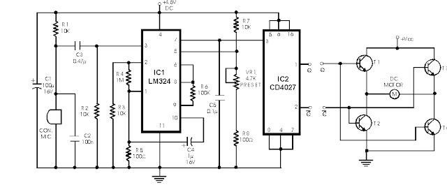
Described here is a very inexpensive solution to many phono-controlled applications like remote switching on, for instance, or activating a camera, tape recorder, burglar alarms, toys, etc. The circuit given here employs a condenser microphone as the pick-up. A two-stage amplifier built around a quad op-amp IC LM324 offers a good gain to enable sound pick-up upto four metres. The third op-amp is configured as a level detector whose non-inverting terminal is fed with the amplified and filtered signal available at the output of the second op-amp. The inverting input of the third op-amp is given a reference voltage from a potential divider consisting of a 10k resistor and a 4.7k preset. The 100-ohm resistance in series with the potential divider ensures against the mis-triggering of the circuit by noise. Thus by adjusting the preset one can control the sensitivity (threshold) of the circuit. The sensitivity control thus helps in rejecting any external unwanted sounds which may be picked up by the amplifier. The output of the level detector are square pulses which are used to trigger a flip-flop. The 100mF capacitor connected across the supply also helps in bypassing noise.
A well regulated supply is recommended for proper functioning of the circuit because an unregulated supply can cause noise pulses to appear in the supply rails when the circuit changes-over state (especially when a load is connected to the circuit). These pulses can be picked up by the sensitive amplifier which will cause the circuit to again switch-over states, resulting into motor-boating noise.

Since the circuit operates at 4.5V, it can be easily incorporated in digital circuits. Fig. (b) shows how the circuit can be employed to control the direction of a DC motor. The circuit employs four npn transistors. Transistors T1 and T4 have their bases tied together and they switch-on simultaneously when Q output is logic 1. Similarly T2 and T3 conduct when Q output is logic 1. Thus current through the motor changes direction when the flip-flop toggles. Filters connected in the circuit and tuned to different bands of audio frequencies will enable the same circuit to control more than one device. For instance, a high frequency sound (such as whistle) can switch on device 1 and a low frequency sound (such as clapping) can control device 2.

Ultrasonic pest repellent


It is well know that pests like rats, mice etc are repelled by ultrasonic frequency in the range of 30 kHz to 50 kHz. Human beings cant hear these high-frequency sounds. Unfortunately, all pests do not react at the same ultrasonic frequency. While some pests get repelled at 35 kHz, some others get repelled at 38 to 40 kHz. Thus to increase the effectiveness, frequency of ultrasonic oscillator has to be continuously varied between certain limits. By using this circuit design, frequency of emission of ultrasonic sound is continuously varied step-by-step automatically. Here five steps of variation are used but the same can be extended up to 10 steps, if desired. For each clock pulse output from op-amp IC1 CA3130 (which is wired here as a low-frequency square wave oscillator), the logic 1 output of IC2 CD4017 (which is a well-known decade counter) shifts from Q0 to Q4 (or Q0 to Q9). Five presets VR2 through VR6 (one each connected at Q0 to Q4 output pins) are set for different values and connected to pin 7 of IC3 (NE555) electronically. VR1 is used to change clock pulse rate. IC3 is wired as an astable multivibrator operating at a frequency of nearly 80 kHz. Its output is not symmetrical. IC4 is CD4013, a D-type flip-flop which delivers symmetrical 40kHz signals at its Q and Q outputs which are amplified in push-pull mode by transistors T1, T2, T3 and T4 to drive a low-cost, high-frequency piezo tweeter. For frequency adjustments, you may use an oscilloscope. It can be done by trial and error also if you do not have an oscilloscope. This pest repeller would prove to be much more effective than those published earlier because here ultrasonic frequency is automatically changed to cover different pests and the power output is also sufficiently high. If you want low-power output in 30-50 kHz ultrasonic frequency range then the crystal transducer may be directly connected across Q and Q outputs of IC4 (transistor amplifier is not necessary).

 
Design by Free WordPress Themes | Bloggerized by Lasantha - Premium Blogger Themes | cheap international calls