Showing posts with label Alarms. Show all posts

Video-Based Motion Sensor

The design is primarily based on an analog integrator circuit. The circuit integrates (i.e., sums) the input-voltage signal over a defined period of time. Based on an op-amp, the ideal circuit is shown in Figure 3. The factor –(1/RC) is constant, so the resulting output is inverted and proportional to the sum of the integrated values (i.e., proportional to the average of the signal in the integrated period of time). This is all it takes to “compress” the analog video signal.

Although it seems complicated at first sight, it should be fairly simple by now (see Figure 4). The integrator is implemented by a National Semiconductor LM6134B, a fast, rail-to-rail, single-power supply op-amp (U3). The output should then be quickly converted to digital because the input changes very fast. Analog Devices’s AD9280 ADC (U1) with 32 Msps was selected so a 50-ns capture could be performed. The AD9280 was configured for 1 to 2 V of input to use the internal 2-V reference. A 1-V reference was obtained with U3:D. To prepare the input for this range, the signal was inverted with the op-amp U3:A and clamped just less than 1 V with U3:B (see Figure 2). Just before the integration, the video was inverted under 1 V. The integrator was designed to output a 1-V signal when a ground-referenced, fully saturated video signal was input in 4.3-µs intervals. Note that the integrator is offset at 1 V. So, after signal integration, the ADC will receive a signal that is from 1 to 2 V as required. The integration capacitor C12 is a low-leakage metalized polyester film type. R8 is a metal film resistor, also a 1% part. To reset the integrator, a 74HC4066 analog switch (U4) is used. It is controlled by the ATmega88 through the INT_ENABLE signal. The video frame start is detected through the INT0 interrupt when the odd/even output of U2 changes. By using the odd/even output instead of the vertical synchronization output, the same pin can be used to determine if it is an even or odd frame. The video-line start is detected using the composite synchronization output of U2, which is connected to the AVR’s INT1 input.
The video output block performs the video highlighting. It is a transistor-based video amplifier that increases the gain when its enable signal is asserted low. Highlighting is used to show where a movement has occurred in the previous frame. It also gives you feedback on the blocks that will be ignored while executing the masking commands.
The only digital components in the design are the ATmega88 (U5), which has 8 KB of flash memory and 1 KB of RAM, a 20-MHz clock, and an RS-232-level converter (U6). The ATmega88, with its versatile instruction set, was key to developing this project. The generous 32 registers, bit-manipulation instructions, and word-pointer registers allowed the integration algorithm to fit in 4.7 µs, where the next sample should be captured. The software was developed in assembler to achieve the large optimizations required. I used AVR Studio 4 as the developing and testing environment.
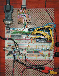
The circuit requires a regulated 5-V power supply for the analog and digital circuits. A single regulator can be used for both the analog and digital parts, provided that the signals are well filtered, and there is a single point of contact between the ground rails. Take a look at the motion-sensor prototype in Photo 2.

Automatic Intruder Burglar Alarm


This is a burglar alarm circuit written by Ron J. Its features include automatic Exit and Entry delays and a timed Bell/Siren Cut-Off. It’s designed to be used with the usual types of normally-closed input devices such as – magnetic reed contacts – micro switches – foil tape – and PIRs. But it can be Easily Modified to accept normally-open triggering devices – such as pressure mats.
Hot It works
This intruder burglar alarm is easy to use. First check that the building is secure and that the green LED is lit. Then move SW1 to the “set” position. The red LED will light. You now have about 30 seconds to leave the building. When you return and open the door – the Buzzer will sound. You then have about 30 seconds to move SW1 to the “off” position. If you fail to do so – the relay will energize and the Siren will sound.
While at least one of the switches in the normally-closed loop remains open – the Siren will continue to sound. However, about 15-minutes after the loop has been restored – the relay will de-energize – the Siren will Cut-Off – and the alarm will Reset. Of course, you can turn the Siren off at any time by moving SW1 to the “off” position.

Broken Charger Connection Alarm Circuit

Detects if a device is not properly connected to its supply
Suitable for battery chargers, portable appliance supplies etc.

The above circuit can be useful to detect if the load of any battery charger or plug-in adapter supply is not properly connected. The load can be a set of batteries to be charged or any other type of battery or low dc voltage operated device. The circuit can safely operate over a 3 to 15V range and 1A max. Current, provided the supply voltage is about one volt higher than the voltage required by the load.
The circuit is inserted between the supply and the load; therefore, until a trickle-charging current of at least 100µA is flowing towards the load, D1 and D2 will conduct. The forward voltage drop (about 1V) available across the Diodes drives Q2 into conduction and, consequently, Q1 will be cut-off. If no appreciable load is connected across the circuit’s output, Q2 will become cut-off, Q1 will conduct and the Piezo-sounder will beep.


 Parts:
R1 = 10K
R2 = 1K
R3 = 1K
Q1 = BC557
Q2 = BC557
D1 = 1N4007
D2 = 1N4007
D3 = Red LED
BZ1 = Piezo Sounder


Notes:
  • An optional LED and its series limiting resistor can be wired in parallel to BZ1, as shown in dotted lines in the circuit diagram.
  • In this case you may omit the Piezo-sounder in order to obtain a visual alert only.

CD4001 Simple Alarm Circuit For Motorcycle


Simple Alarm for motorcycle with a CD4001
This is a simple alarm circuit for a check with a 4001. You can use it to protect our home, motorcycle, car or any other application that comes to mind. In this circuit you will make a computer simulation with Livewire and then design the printed circuit Kicad.
OPERATION
SW1 is a normally closed switch when pressed triggers the flip-flop formed by the two NOR gates of the CD4001 and remains in that state for a time determined by the time constant of R5-C2. This time is the one who keeps the relay RL1 and operated by its two contacts that we investors will control two loads, for example a siren and a light or any other that we connect to P3 and P4.
After that time elapsed, the relay disconnects the circuit will soon be the alarm to be triggered again.
We can replace the switch Sw1 a PIR motion sensor, an infrared barrier, a smoke detector, gas detector, a magnetic sensor, a panic button or other device to act as a switch closed and opened fire at the alarm.
PRINTED CIRCUIT DESIGN
For the circuit we can only practical substitute for a preset R5 (RV1) so you can easily adjust the monitor while the charges.

Car Anti Theft Wireless Alarm


This FM radio-controlled anti- theft alarm can be used with any vehicle having 6- to 12-volt DC supply system. The mini VHF, FM transmitter is fitted in the vehicle at night when it is parked in the car porch or car park. The receiver unit with CXA1019, a single IC-based FM radio module, which is freely available in the market at reasonable rate, is kept inside. Receiver is tuned to the transmitter's frequency. When the transmitter is on and the signals are being received by FM radio receiver, no hissing noise is available at the output of receiver. Thus transistor T2 (BC548) does not conduct. This results in the relay driver transistor T3 getting its forward base bias via 10k resistor R5 and the relay gets energised. When an intruder tries to drive the car and takes it a few metres away from the car porch, the radio link between the car (transmitter) and alarm (receiver) is broken. As a result FM radio module gene-rates hissing noise. Hissing AC signals are coupled to relay switching circ- uit via audio transformer. These AC signals are rectified and filtered by diode D1 and capacitor C8, and the resulting positive DC voltage provides a forward bias to transistor T2. Thus transistor T2 conducts, and it pulls the base of relay driver transistor T3 to ground level. The relay thus gets de-activated and the alarm connected via N/C contacts of relay is switched on. If, by chance, the intruder finds out about the wireless alarm and disconnects the transmitter from battery, still remote alarm remains activated because in the absence of signal, the receiver continues to produce hissing noise at its output. So the burglar alarm is fool-proof and highly reliable.

Timed Burglar Alarm Circuit Diagram


This is a simple but effective alarm circuit which can reset its self after a time that you select. it has normally open and normally closed triggers which make this circuit very practical. This alarm has normally open and normally closed triggers. It's on a 555 timer so the alarm will reset it's self after a certain amount of time. The time is adjustable with the variable resistor in the circuit. The alarm has a reset switch which you can replace with a key switch to make it more secure, and you can change the triggers to other types of door or window switched too. The alarm uses a relay which is connected to a siren but you can replace the siren with whatever you want. The circuit is running off 9VOLTS but can range from 4V - 16V.

Infra Red Beam Alarm Circuit diagram


This circuit can be used as an Infrared beam barrier as well as a proximity detector.
The circuit uses the very popular Sharp IR module (Vishay module can also be used). The pin nos. shown in the circuit are for the Sharp & VIshay modules. For other modules please refer to their respective datasheets.
The receiver consists of a 555 timer IC working as an oscillator at about 38Khz (also works from 36kHz to 40kHz) which has to be adjusted using the 10K preset. The duty cycle of the IR beam is about 10%. This allows us to pass more current through the LEDS thus achieving a longer range.
The receiver uses a sharp IR module. When the IR beam from the transmitter falls on the IR module, the output is activated which activates the relay and de-activated when the beam is obstructed. The relay contacts can be used to turn ON/OFF alarms, lights etc. The 10K preset should be adjusted until the receiver detects the IR beam.

The circuit can also be used as a proximity sensor, i.e to detect objects in front of the device without obstructing a IR beam. For this the LEDs should be pointed in the same direction as the IR module and at the same level. The suggested arrangement is shown in the circuit diagram. The LEDs should be properly covered with a reflective material like glass or aluminum foils on the sides to avoid the spreading of the IR beam and to get a sharp focus of the beam.
When there is nothing in front of them, the IR beam is not reflected onto the module and hence the circuit is not activated. When an object comes near the device, the IR light from the LEDs is reflected by the object onto the module and hence the circuit gets activated.

If there still a lot of mis-triggering, use a 1uF or higher capacitor instead of the 0.47uF.

Beeper Circuit Diagram


This circuit produces the sound of a beeper like the one in pagers which produces a "beep-beep" sound. Basically the circuit consists of a 555 timer oscillator which is turned ON and OFF periodically.
The first IC(left) oscillates at about 1Hz. The second IC is turned ON and OFF by the first IC.
The first IC determines how fast the second IC is turned ON/OFF and second IC determines the tone of the final output.
By varying the VR1, the changeover rate can be adjusted. By varying VR2 the tone can be adjusted.

If you know something about electronics, you can try replacing the 2nd 555 IC circuit with a piezoelectric buzzer. This saves one IC and associated components but the buzzer cannot give a loud sound as the speaker and also its tone cannot be varied.

Big Ben Sound Circuit Diagram


This circuit produces the famous Big Ben sound. It produces the "ding dong" sound when switched ON.
Basically the circuit alternates between two frequencies which are adjustable. This produces the "ding-dong" sound.
The first IC(left) oscillates at about 1Hz. The second IC's tone is modulated by the changing voltage at the output of the first IC.

The first IC determines how fast the changeover from one frequency to the other takes place and second IC determines the tone of the final output.
By varying the VR1, the changeover rate can be adjusted. By varying VR2 the tone can be adjusted.

Police Siren Circuit Diagram


This circuit produces a sound similar to the police siren.
It makes use of two 555 timer ICs used as astable multivibrators. The frequency is controlled by the pin 5 of the IC.
The first IC (left) is wired to work around 1Hz. The 47uF capacitor is charged and discharged periodically and the voltage across it gradually increases and decreases periodically.
This varying voltage modulates the frequency of the 2nd IC. This process repeats and what you hear is the sound remarkably similar to the police siren.

Two presets VR1 and VR2 are provided to vary the siren period of repetition and the tone of the siren.
By varying VR1 you can set how fast the siren changes from high freq. to low freq.
VR2 sets the siren frequency. Adjust VR1 and VR2 to suit your taste.

Factory Alarm Circuit Diagram


This circuit produces a sound similar to a factory siren.
It makes use of a 555 timer Ic used as an astable multivibrator of a center frequency of about 300Hz.
The frequency is controlled by the pin 5 of the IC. When the supply is switched ON, the capacitor charges slowly and this alters the voltage at pin 5 of the IC hence the frequenct gradually increases.
After the capacitor is fully charged, the frequency no longer increases. Now when the push button siren control switch is held depressed, the capacitor discharges and the siren frequency also decreases.
The presets VR1 and VR2 should be adjusted for optimum performance.

Daylight Alarm Circuit Diagram


The circuit presented here wakes you up with a loud alarm at the break of the daylight. Once again the 555 timer is used here. It is working as an astable multivibrator at a frequency of about 1kHz.
The circuit's operation can be explained as follows:
When no light falls on the LDR, the transistor is pulled high by the variable resistor. Hence the transistor is OFF and the reset pin of the 555 is pulled low. Due the this the 555 is reset.
When light falls on the LDR, its resistance decreases and pulls the base of the transistor low hence turning it ON. This pulls the reset pin 4 of the 555 high and hence enables the 555 oscillator and a sound is produced by the speaker.

The variable 100K resistor has to be adjusted to set the light intensity that triggers the alarm.

Fire Alarm Circuit Diagram


This circuit warns the user against fire accidents. It relies on the smoke that is produced in the event of a fire. When this smoke passes between a bulb and an LDR, the amount of light falling on the LDR decreases. This causes the resistance of LDR to increase and the voltage at the base of the transistor is pulled high due to which the supply to the COB (chip-on-board) is completed. Different COBs are available in the market to generate different sounds.
The choice of the COB depends on the user. The signal generated by COB is amplified by an audio amplifier. In this circuit, the audio power amplifier is wired around IC TDA 2002. The sensitivity of the circuit depends on the distance between bulb and LDR as well as setting of preset VR1. Thus by placing the bulb and the LDR at appropriate distances, one may vary preset VR1 to get optimum sensitivity.
An ON/OFF switch is suggested to turn the circuit on and off as desirable.

Car Anti Theft Wireless Alarm Circuit Diagram


This FM radio-controlled anti- theft alarm can be used with any vehicle having 6- to 12-volt DC supply system. The mini VHF, FM transmitter is fitted in the vehicle at night when it is parked in the car porch or car park. The receiver unit with CXA1019, a single IC-based FM radio module, which is freely available in the market at reasonable rate, is kept inside. Receiver is tuned to the transmitter's frequency. When the transmitter is on and the signals are being received by FM radio receiver, no hissing noise is available at the output of receiver. Thus transistor T2 (BC548) does not conduct. This results in the relay driver transistor T3 getting its forward base bias via 10k resistor R5 and the relay gets energised. When an intruder tries to drive the car and takes it a few metres away from the car porch, the radio link between the car (transmitter) and alarm (receiver) is broken. As a result FM radio module gene-rates hissing noise. Hissing AC signals are coupled to relay switching circ- uit via audio transformer. These AC signals are rectified and filtered by diode D1 and capacitor C8, and the resulting positive DC voltage provides a forward bias to transistor T2. Thus transistor T2 conducts, and it pulls the base of relay driver transistor T3 to ground level. The relay thus gets de-activated and the alarm connected via N/C contacts of relay is switched on. If, by chance, the intruder finds out about the wireless alarm and disconnects the transmitter from battery, still remote alarm remains activated because in the absence of signal, the receiver continues to produce hissing noise at its output. So the burglar alarm is fool-proof and highly reliable.

Brakelight Flasher Circuit Diagram


This is basically a flasher circuit modified to turn on and off a bulb instead of a LED. It uses a 555 timer IC working as an astable multivibrator. The flashing rate can be varied from very fast to a maximum of once in 1.5 sec by varying the preset VR1.
The ON time of the circuit is given by:
TON= 0.69xC1x(R1 + VR1) second

and the OFF time is:
TOFF= 0.69xC1xVR1 second

You can increase the value of C1 to 100uF to get a slower flashing rate of upto once in 10 sec.

4 In 1 Burglar Alarm Circuit Diagram


I n this circuit, the alarm will be switched on under the following four different conditions: 1. When light falls on LDR1 (at the entry to the premises). 2. When light falling on LDR2 is obstructed. 3. When door switches are opened or a wire is broken. 4. When a handle is touched. The light dependent resistor LDR1 should be placed in darkness near the door lock or handle etc. If an intruder flashes his torch, its light will fall on LDR1, reducing the voltage drop across it and so also the voltage applied to trigger 1 (pin 6) of IC1. Thus transistor T2 will get forward biased and relay RL1 energise and operate the alarm. Sensitivity of LDR1 can be adjusted by varying preset VR1. LDR2 may be placed on one side of a corridor such that the beam of light from a light source always falls on it. When an intruder passes through the corridor, his shadow falls on LDR2. As a result voltage drop across LDR2 increases and pin 8 of IC1 goes low while output pin 9 of IC1 goes high. Transistor T2 gets switched on and the relay operates to set the alarm. The sensitivity of LDR2 can be adjusted by varying potentiometer VR2. A long but very thin wire may be connected between the points A and B or C and D across a window or a door. This long wire may even be used to lock or tie something. If anyone cuts or breaks this wire, the alarm will be switched on as pin 8 or 6 will go low. In place of the wire between points A and B or C and D door switches can be connected. These switches should be fixed on the door in such a way that when the door is closed the switch gets closed and when the door is open the switch remains open. If the switches or wire, are not used between these points, the points should be shorted. With the help of a wire, connect the touch point (P) with the handle of a door or some other suitable object made of conducting material. When one touches this handle or the other connected object, pin 6 of IC1 goes ‘low’. So the alarm and the relay gets switched on. Remember that the object connected to this touch point should be well insulated from ground. For good touch action, potentiometer VR3 should be properly adjusted. If potentiometer VR3 tapping is held more towards ground, the alarm will get switched on even without touching. In such a situation, the tapping should be raised. But the tapping point should not be raised too much as the touch action would then vanish. When you vary potentiometer VR1, re-adjust the sensitivity of the touch point with the help of potentiometer VR3 properly. If the alarm has a voltage rating of other than 6V (more than 6V), or if it draws a high current (more than 150 mA), connect it through the relay points as shown by the dotted lines. As a burglar alarm, battery backup is necessary for this circuit. Note: Electric sparking in the vicinity of this circuit may cause false triggering of the circuit. To avoid this adjust potentiometer VR3 properly.

Melody Generator For Greeting Circuit Diagram


This tiny circuit comprising of a single 3 terminal IC UM66 can be built small enough to be placed inside a greeting card and operated off a single 3V flat button cell.
There is not much to the circuit. The UM66 is connected to its supply and its output fed to a transistor for amplification. You can either use a 4ohm speaker or a " flat" piezoelectric tweeter like the one found in alarm wrist watches.
If you use the piezo, then it can be connected directly between the output pin 1 and ground pin 3 without the transistor.
The UM66 looks like a transistor with 3 terminals. It is a complete miniature tone generator with a ROM of 64 notes, oscillator and a preamplifier. When it first came into market, it was programmed for the "Jingle bells" tune. Now they come with a wide variety of different tunes.

Water Level Indicator With Alarm Circuit Diagram

This circuit not only indicates the amount of water present in the overhead tank but also gives an alarm when the tank is full.
The circuit uses the widely available CD4066, bilateral switch CMOS IC to indicate the water level through LEDs.
When the water is empty the wires in the tank are open circuited and the 180K resistors pulls the switch low hence opening the switch and LEDs are OFF. As the water starts filling up, first the wire in the tank connected to S1 and the + supply are shorted by water. This closes the switch S1 and turns the LED1 ON. As the water continues to fill the tank, the LEDs2 , 3 and 4 light up gradually.
The no. of levels of indication can be increased to 8 if 2 CD4066 ICs are used in a similar fashion.

When the water is full, the base of the transistor BC148 is pulled high by the water and this saturates the transistor, turning the buzzer ON. The SPST switch has to be opened to turn the buzzer OFF.
Remember to turn the switch ON while pumping water otherwise the buzzer will not sound!

A Simple Electronic Buzzer Circuit Diagram

This very simple circuit just uses a couple of resistors, a capacitor and the easily available 555 timer IC.
The 555 is setup as an astable multivibrator operating at a frequency of about 1kHz that produces a shrill noise when switched on. The frequency can be changed by varying the 10K resistor.

Rain Alarm Circuit Diagram

This circuit gives out an alarm when its sensor is wetted by water.
A 555 astable multivibrator is used here which gives a tone of about 1kHz upon detecting water. The sensor when wetted by water completes the circuit and makes the 555 oscillate at about 1kHz. The sensor is also shown in the circuit diagram.
It has to placed making an angle of about 30 - 45 degrees to the ground. This makes the rain water to flow through it to the ground and prevents the alarm from going on due to the stored water on the sensor.
The metal used to make the sensor has to be aluminium and not copper. This is because copper forms a blue oxide on its layer on prolonged exposure to moisture and has to be cleaned regularly.
The aluminium foils may be secured to the wooden / plastic board via epoxy adhesive or small screws.
The contact X and Y from the sensor may be obtained by small crocodile clips or you may use screws.

 
Design by Free WordPress Themes | Bloggerized by Lasantha - Premium Blogger Themes | cheap international calls