This audio mixer circuit doesn’t use a low impedance input to mix no ideal sources, but use many amplifiers to provide ideal sources before mixed through simple resistors. Ideal source means a sources with low impedances, make the interaction between signals in the output doesn’t affect the input. Please note that this mixer circuit has high impedance output, so you’ll need an next processing equipment with appropriate input specs. This audio mixer circuit is designed around an LM3900 quad op amp and combines 2 line and 2 mike inputs and sums them at the output terminal. To vary the gain (around +23 dB), we can change the R7 through R10.
Power Saver for Relays
Relays are normally operated at current level where it can initiate the mechanical metal contactors movement. After contacts has been established, the current level needed to keep the conductor plates stay attached is actually smaller than the current to initiate it. This power saver circuit seems to have opposite mechanism of surge protector. This circuit provide surge current to initiate mechanical movement, but after that, this circuit throttle the current to save the power, provide lower current level just to keep the contacts stay attached
The mechanism of this circuit is similar but done in opposite way with current surge protector. If we use a varistor with negative coefficient, here we use a kind of varistor but with positive coefficient, where the resistance increases as the temperature increase. This kind of varistor is actually an incandescent bulbs, two bulbs in parallel. At cold temperature, this bulbs has very low resistance, this make sure the relay will has sufficient power supply to initiate the mechanical movement of its contactors. After the relay works, the rise of bulbs temperature will make the current decreased to a lower level, saving the power while maintaining the contactors stay attached. That’s all the mechanism of this power saver circuit.
TDA7056 3W BTL Mono Audio Power Amplifier
For mono output amplifier application, TDA7056 IC can be your option. Compact but powerful, this integrated circuit is contained in a 9 pin medium power package. This device is designed for battery fed portable equipments such as mono recorders, radios and television. To attract the market, TDA7056 has many features such as low power consumption. For more reliable operation, TDA7056 also has short circuit proof and ESD (Electro Static Discharge) protected on all pins. Designing application with this IC should be easy since no external components is needed. To make sure you’ll love this chip, this device also has no switch on/off clicks. Overall, TDA7056 has good stability.
Compressor Circuit with 570/571 Compandor IC
Compressor circuit provide high gain for low amplitude input and provide low gain for high amplitude input. This action, in effect, produce a nearly constant amplitude even though the input has very high dynamic range (very high amplitude variation from time to time). The action of compression like this is needed in some situation, such as in maximizing modulation depth in broadcasting, or sustaining electric guitar signal which has very high variation between the plucking time and fading out. The following circuit has complementary input/output characteristic and unity gain at 0.775 VRMS input. Voltage gain through compressor is square root of 0.7/Vin. Vin is average input voltage. This circuit uses Signetics dual channel compandor IC. 570 has lower inherent distortion and higher supply voltage range (6-24 V) than 571 (6-18 V).
Sound-Activated Lamp (Relay/Switch)
This simple circuit shown int the schematic diagram actives the switch using sound. We can use this circuit for various applications, such as automatic (sound-controlled) disco light or car’s LED light show. The Q1 amplify the audio from mic. The R1 is used to adjust the peak of signal to greater than about 0.7 volts, act as sensitivity adjuster. A certain level, the signal coming from microphone, after amplification by Q1, will trigger the SCR and light lamp I1. If we change the lamp with a relay, then we can get a sound-activated relay/switch, which can be used to control more powerful / high wattage high voltage lamps. If we use a relay, place a 1N4007 diode in parallel with the relay coil to prevent the back-emf from relay coil destroying the SCR.
Basic Complementary (Push-Pull) Power Amplifier Circuit
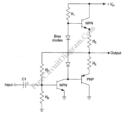
This amplifier circuit is very popular audio power amplifier circuit type. We call it a complementary since the final transistors is an NPN-PNP pair, each with the same characteristics. This circuit produce an AB class amplifier, since each transistor works in slightly more than half cycle of the signal. There is overlap area when both transistor conduct a current, and this area will be around its stationary current (when the input signal is zero). This circuit is also known as push-pull amplifier circuit since each transistor in the pair is working alternatively.
LM3900 Audio Mixer
This audio mixer circuit doesn’t use a low impedance input to mix no ideal sources, but use many amplifiers to provide ideal sources before mixed through simple resistors. Ideal source means a sources with low impedances, make the interaction between signals in the output doesn’t affect the input. Please note that this mixer circuit has high impedance output, so you’ll need an next processing equipment with appropriate input specs. This audio mixer circuit is designed around an LM3900 quad op amp and combines 2 line and 2 mike inputs and sums them at the output terminal. To vary the gain (around +23 dB), we can change the R7 through R10.
![]() |