The design is primarily based on an analog integrator circuit.
The circuit
integrates (i.e., sums) the input-voltage signal over a defined period
of time. Based on an op-amp, the ideal circuit is shown in Figure 3. The
factor –(1/RC) is constant, so the resulting output is inverted and
proportional to the sum of the
integrated values (i.e., proportional to the average of the signal in the integrated period of time). This is all it takes to “compress” the analog
video signal.
 Although
 it seems complicated
at first sight, it should be fairly simple by now (see Figure 4). The integrator is implemented by a
National Semiconductor LM6134B, a fast, rail-to-rail, single-
power supply
op-amp (U3). The output should then be quickly converted to digital
because the input changes very fast. Analog Devices’s AD9280 ADC (U1)
with 32 Msps was selected so a 50-ns capture could be performed. The
AD9280 was configured for 1 to 2 V of input to use the internal 2-V
reference. A 1-V reference was obtained with U3:D. To prepare the input
for this range, the signal was inverted with the op-amp U3:A and clamped
just less than 1 V with U3:B (see Figure 2). Just before the
integration, the video was inverted under 1 V. The integrator was
designed to output a 1-V signal when a ground-referenced, fully
saturated video signal was input in 4.3-µs intervals. Note that the
integrator is offset at 1 V. So, after signal integration, the ADC will
receive a signal that is from 1 to 2 V as required. The integration
capacitor
C12 is a low-leakage metalized polyester film type. R8 is a metal film
resistor, also a 1% part. To reset the integrator, a 74HC4066 analog
switch (U4) is used. It is
controlled by the ATmega88 through the INT_ENABLE signal.
The
video frame start is detected through the INT0 interrupt when the
odd/even output of U2 changes. By using the odd/even output instead of
the vertical synchronization output, the same pin can be used to
determine if it is an even or odd frame. The video-line start is
detected using the composite synchronization output of U2, which is
connected to the AVR’s INT1 input.
The video output block performs the video highlighting. It is a
transistor-based video amplifier that increases the gain when its enable
signal is asserted low. Highlighting is used to show where a movement
has occurred in the previous frame. It also gives you feedback on the
blocks that will be ignored while executing the masking commands.
The only digital components in the design are the ATmega88 (U5),
which has 8 KB of flash memory and 1 KB of RAM, a 20-MHz clock, and an
RS-232-level converter (U6). The ATmega88, with its versatile
instruction set, was key to developing this project. The generous 32
registers, bit-manipulation instructions, and word-pointer registers
allowed the integration algorithm to fit in 4.7 µs, where the next
sample should be captured. The software was developed in assembler to
achieve the large optimizations required. I used AVR Studio 4 as the
developing and testing environment.
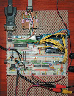
The circuit requires a regulated 5-V power supply for the
analog and digital circuits. A single regulator can be used for both the analog and digital
parts, provided that the signals are well filtered, and there is a
single point of contact between the ground rails. Take a look at the
motion-sensor prototype in Photo 2.


