Audio level meter (vumeter)


This circuit uses just one IC and a very few number of external components. It displays the audio level in terms of 10 LEDs. The input voltage can vary from 12V to 20V, but suggested voltage is 12V.
The LM3915 is a monolithic integrated circuit that senses analog voltage levels and drives ten LEDs  providing a logarithmic 3 dB/step analog display. LED current drive is regulated and programmable, eliminating the need for current limiting resistors.

The IC contains an adjustable voltage reference and an accurate ten-step voltage divider. The high-impedance input buffer accepts signals down to ground and up to within 1.5V of the positive supply. Further, it needs no protection against inputs of 35V. The input buffer drives 10 individual comparators referenced to the precision divider. Accuracy is typically better than 1 dB.

Obstruction Detector With 12C508 IR


Description
This project is inspired by the DPRG IRPROX project. They have a pretty good PCB layout and idea. I would like to thank them for posting their project for all of us to see and learn from, I wouldn’t have started PIC programming without them, or at least not nearly as quickly come up to speed! The pinout on my board allows either a five-wire or a four-wire connection to be made the former uses a disable line if desired. You can also put in a resistor or use a trimpot to adjust range. The trimpot locations are very generic, most pots will fit. Be careful not to adjust pot to 0 ohms! The IR proximity detector works very well, even in a brightly lit “noisy” environment. Instead of modulating the IR LED for 600us and then looking for a detection, I now look for a detection after every on/off cycle of an IR LED and count the number of hits that I get. I also look during the ‘off’ cycle when none of the IR LEDs are on and count the number of false hits that I get there. If I get more good hits than false hits then I say its a true detection. I then increment a counter as a sort of timer, when it passes a certain threshold, I notify a hit. At this time I check to make sure that a minimum number of good hits has been attained. At the same time I keep track via another time-out counter of noise hits. When this counter passes a certain threshold it then removes any detection that has been set. I fiddled a lot with the various threshold values for minimum number of good hits, time-out values and divisors for updating the false hit counts, and finally settled on the ones that currently used. I’m calling it a success and moving on to other projects! The source code for the, uhm, DLC IR proximity detector can be downloaded below as well as the PDF documentation for this kit.

Proximity Detector Circuit Based 555 IR


Description Sometimes you want a simple solution to a problem and you don’t mind if your main controller has to do the work. This IRPD requires the main robot processor to choose which side to look at, and requires it to “debounce” the results for reliably operation. But, it still works really well without any complex program code.
The NAND gate is a standard 74LS00 that you can get anywhere – even Radio Shack, same with the 555, IR detector (RS Everlight or Sharp GP1U58Y) and IR LEDs can also be gotten at Radio Shack. Parts are easy to find and simple to connect. This does not require any fancy wiring or parts placement. Make sure that you use a .1uf bypass cap next to the 555 and next to the IR demodulator. Tweak the 2K pot until you have 38KHz, if you have a ‘scope, this is a 1/38,000 period, or about 26.3us. If you are using a Parallax Basic Stamp II for your robotic controller, you can feed the output of the 555 in an I/O port and measure the frequency very easily. The code to do this is below. It assumes that you are using port 7 as the 555 input port.
‘Basic Stamp II Freq Counter
O555    con        7
freq    var        word Loop:
count O555,100,freq
debug dec5 freq*10,cr
goto Loop
One of the nifty things that make the 555 circuit fun to use is that you can use it to do IR communications with other devices that read IR at 38KHz! If you run pin 4 of the 555 to a Stamp II port instead of just tying it high, you can use the serout Stamp II command to modulate the IR in such a fashion that other IR demodulator equiped devices can read it! I’ve done it, it works – Have fun.

High Voltage Generator/Solid State Tesla Coil


Parts
R1 27 Ohm 5W Resistor or 27 Ohm 10W Resistor
R2 240 Ohm 5W Resistor or 240 Ohm 10W Resistor
BR1 50 Volt, 6 Amp Bridge Rectifier
C1 8000uf, 35 Volt Capacitor
Q1, Q2 2N3055 NPN Power Transistor
T1 24V 5A Transformer (See “Notes”)
T2 TV Flyback Transformer (See “Notes”)
S1 115V 3A SPST Switch
MISC Case, Wire, Heatsinks, Line Cord
Notes
1. T2 is a high voltage flyback transformer salvaged from an old TV, or ordered from Fair Radio Sales (see Where To Get Parts). Look for the biggest, most intimidating transformer you can find. Old tube TV’s are a good place to look. The transformer should not have a rectifier built in.
2. You will need to rewind the transformer’s primary. First, remove the old primary, being careful not to damage the high voltage secondary. If the transformer is wound with all windings incased in plastic, use another transformer. Second, wind on 5 turns of 18 AWG wire, twist a loop (center tap), and then wind on 5 more turns. This becomes winding C-D. Now, wind on 2 turns of 22 AWG wire, twist a loop, and wind on 2 more turns. This becomes winding A-B.
3. Q1 and Q2 will run HOT if not used with a large heatsink. After the circuit has been running for a minute or two, you should still be able to put your finger on the transistors without being burnt. Also, R1 and R2 will run hot.
4. If you experience arcing on the exposed transformer leads, select a lower voltage for T1. If you are powering the circuit with a power supply (see Power Supply), just crank down the voltage.
5. For a real high voltage output, connect a voltage multiplier (from an old TV or computer monitor) to the output of T2.
6. If the circuit does not work, reverse connections A and B.
7. I finally got around to taking some pictures of the circuit in operation.

Several RC5 Infrared Transmitter Circuit

 1-channel transmitter with 16 selectable codes (PIC12C508)

RC5 is not suitable as a barrier to race out to whoever is the winner. Two or more RC5 channel interfere with each other and the protocol itself also takes time for the transfer. If more than one car with RC5 transmitter arrive close together, it can well be the first and the second triggers the stopwatch. IR does not pass through optical barriers through. Two car side by side is thus not before. Infrared is used in daylight outside, not really a good idea (the sun bothers!). With luck we can get a LOT still to reach 3m. Some wondered whether it was possible to hold down the button to send continuously or only one output to switch as long as a button is pressed. Is it possible that an output remains active for a certain time only? Yes, of course, is all that. This must DU EVEN each program change. I do not do that for you.
If the recipients are TSOP1836 TSOP1736 and specified. You need of course only one of them.
Which of the two is better? No idea.
After I had finished the RC5 tester, I have also done the same because a station building itself. The first attempt I have made with a PIC16F873. I used the PWM module to generate the frequency of 36kHz. Worked fine, but actually that was all much too large for a single channel. The 36kHz can also hold smaller produce PIC’s. These recipients are then a whole family of channels and come out.
On the function of the transmitter:
The PIC’s run in sleep mode until a key is pressed. The power consumption is then under 1uA. The circuit can then switch to the battery for a long time be without. Even with 3V button cells, the device should work very long.
When a button is pressed, the distance will be five RC5-wave pulse sent from the 50ms. That should suffice for the recipient to receive the code. After the PIC goes back into sleep mode. There is no repeat of the keys. This prevents the battery is discharged which when a key is pressed constantly unintentionally. All channels use the device code 29 to VCR, TV or CD player is not interfering.
! Attention!
In contrast to “normal” RC5 remotes do I change the toggle bit is not in any keystroke. Each key has a separate toggle. This is easier to force the receiver. It is therefore not possible, the receiver with a RC5 remote control to use! It is only with my stations.
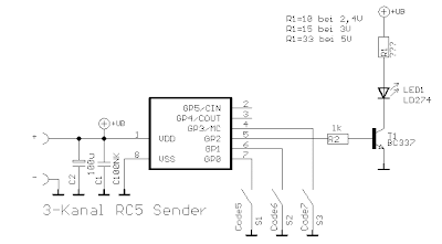
For short distances, the LED directly from R2 (then 150 ohms or greater) to be connected and ground. The proposed power amplifier current is of about 100mA. Some of my remotes blow up to 250mA through the LED. For 5V could to increase the transmission power, a second LED in series with LED1. R1 is then 22 ohms.

About J0-3, the command code to be sent from 0-15 are set in binary code. Before each mission, the jumpers are queried. To send the code can then restart the PIC’s example by an additional circuit to be changed without it. As a clock for the PIC here I use the internal RC-oscillator. The is more precise than I had expected. Between 3V and 5V, it is no problem with the recipient. At 2.5 V (2xNiCd cell) it works but not always. Even at extreme temperatures, there could be problems. There must be a quartz oscillator to GP4 be connected fifth the number of adjustable codes unfortunately falls to four. Source code and internal file I need for rich to.
3-channel transmitter (PIC12C508)

 The transmitter sends the codes 5,6,7. GP4, 5 are open and are not used. Only GP0, 1,3 have internal pullups and can wake the PIC from sleep. the oscillator is the same as for the one-channel transmitter. GP4, 5 but are still free. So no problem.
5-channel transmitter (PIC16F84)

Although still at PORTB inputs are free only PORTB0, 4,5,6,7 used. The PIC can these inputs on an interrupt will wake from sleep only. Therefore, the maximum of five keys.PORTB4, 5,6,7 have internal pullups. The entrance to PORTB0 has no internal pullup resistor. Therefore, an external use. PORTB0 provides the code PORTB4 3 and 7, the codes just 4-7.
16-channel transmitter (PIC16F84)
 This receiver is equivalent to one-channel transmitter intended to be, but can be used with the other stations also. It is suitable when only a single device or set to only one function is to be executed, eg light on / off, central locking open / close. With the jumpers, the codes will be set 0-1.
1-channel receiver with 16 selectable codes (PIC12C508)

40 Watt Fluorescent Strobe Lamp Schematic


Part List:
C1/C2 2x Elko standing 1μF/16V
C3 1x
Ker. Scheibenkondens. 0.1 μF
C4 1x
HV-capacitor 1μF 350V axial
C5 1x
Elko stand. 470μF 25 V
C6 1x
Poly condensation. 0.068 μF 630V
D1-4 4x
Diode 1N4001
D5 1x
Diode 1N4007
L1 1x
Ignition coil (such as the normal speed camera strobe)
P1 1x
Poti 6mm 2.2 M
R1/R4 2x
Resistor 470R 1 / 4 W
R2/R9 2X
Resistor 47K 1 / 4 W
R3 1x
Resistor 10K 1 / 4 W
R5 1x
Resistor 270R 1 / 4 W
R6 1x
Resistor 1.2 K 1 / 4 W
R7 1x
Resistor 22K 1 / 4 W
R8 1x
Resistor 120K 1 / 4 W
Si1 1x
Backup medium time 160mA
Si2 1x
A pair of fuse holders
T1/T2 2x
Transistor BC557B
T3 1x
Transistor BC547B
Ta1 1x
Transformer 2x 2x 5V 500mA 5VA
TA2 1x
Trafo 1,2 VA 9Volt
Th1 1x
Thyristor 4A 400V T0220
TR1 1x
Triac 4A 400V T0220
The points J1 and J2 to connect with the two electrodes on one side of the fluorescent tube. The points J3 and J4 , connect with the electrodes on the other side. Now stretch a thin insulated!! Wire along the tube and glue it eg. Scotch tape firmly. This wire carries the ignition voltage of several thousand volts to the tube so that they ignite properly. This wire, connect one end with J7 on the board, while the other end must necessarily be isolated. This wire leads except the high voltage pulses that is also voltage. The points with J5 and J6 of the board is one, tube fitting, ballast clamped to (choke, there’s the light trading.) Finally there is the voltage at J8 and J9. Now it should somehow already shine or flash, with the potentiometer, the flash rate can be set.


The circuit works much like the original Strobos. except that a fluorescent tube is used. Thus, the fluorescent tube zündbereit remains constant, the two electrodes of the tube are continuously transformer Ta1 supplied with electricity. This current makes the two resistance wires of the glow tube in, so the mercury evaporates into the tube and the electron emission is simplified. Ta2 Returns on the rectifier “D1-D4 , the voltage of the multivibrator, the ignition frequency of the tube is responsible for. The speed of the AMV is with potentiometer P1 set. The pulse then passes through R3 to T3, is amplified there and controls the bias for the triac, the conducting of these alternates. If so, then the circuit through the tube and the ballast closes and the tube can light up. The pulses of T3 also enter via the capacitor C3 to the gate of the thyristor Th1. Simultaneously with the closing “of the circuit for the tube is Th1 -conductive and creates a short in the ignition coil current flow, which in turn generates a high voltage on the secondary. This voltage of several thousand volts is now operational on port J7 to a wire outside of the tube. The high voltage at the tube provides the necessary starting voltage so that it starts and can certainly light up until the thyristor Th1 locks again.

Hammond Transformers 6V6 Push-Pull Tube Amplifier


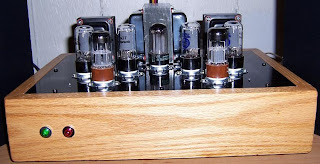
This 6V6 amp was built following the push-pull (PP) EL84 / 6V6 Dynaco A-410 output transformer schematic. There are a few minor deviations from the original schematics. Instead of Dynaco transformers, Hammond 1608A audio output transformers and a Hammond 272HX power transformer were used. The EL84 / 6V6 PP Dynaco A-410 output transformer schematic showed a 1000 ohm feedback resistor which resulted in bad amplifier oscillation. Feedback resistor Values between about 6 and 10 k-ohm worked well and I settled on 10k. A 5Y3 rectifier would have been to small for a stereo amp so a JJ GZ34 rectifier was used. It became necessary to put a 100 ohm resistor before the first power supply capacitor to bring down the B+ to about 325 volts as I was getting in excess of 345 volts (there is less voltage drop through a GZ34 versus a 5Y3).

Atmel at89c51 Office-Home Security System


Home security project
Securiy is a matter of great concern to all of us in this world. Normally there are four types of security threat to our property.
1 )Thief, an inturder.
2)Fire, so we use fire sensor.
3)Water spilage /over flow, so we use water sensor.
4) Gas leak , we use gas sensor, whenever there is security breach from one of above or any combination of above.
The project takes the following action
1) Sounds an ALARM to attract your home Security project
or public attention .
2) If the reset sw is not pressed within 30 seconds the projects takes further action,
3) It makes an emergency call to deliver an emergency message stored in speech IC.
4) It will make five attempts to call you before it checks the conditions again.


Atmel at89c51 Office-Home Security System
The project presented here is based on world’ s most powerful intel’ s mcs-51 family of microcontroller atmel at89c51. CIRCUIT EXPLANATION: This project is based on 8051 microcontroller.(IC2) IC3 and is used as buffer. IC4 is a one time programmable(otp) chip where messages are stored. This is 21 second speech ic where total of 12 messages can be recorded on eight different locations, but total duration should not be more than 21 seconds. Recorded messages can be played back by setting the trigger pin 10 & 11 to high, making these pin low will stop the message, Setting these pin high will repeatedly replay the same message. IC5 is an audio amplifire . Audio output from speech ic(IC4) pin no 7 cout is coupled to this ic on pin no 3 through VR2 volume control and C10. Amplified output from pin no 5 drives the speaker through capacitor C14. R14 and C13 corrects the tone. .C15 and C16 couples the audio message to telephone line. IC4 needs 3.3v operating voltage .R9 is a voltage dropping resistor, D7 is 3.3v zener diode and C7 is a filter capacitor. These components will always maintain the voltage to3.3v at pin 9,12 of IC4. capacitor C8 is a feed back capacitor.,C9 and R13 connected to pin no 7 of IC 4 are tone corrector.R12 along with the VR1 variable resistor performs the sampling rate adjustment. R10 and R11 connected to pin26 and pin 27 of the microcontroller are voltage dropping resistors. R15 and R16 connected to the base of transister Q1 and Q2 are voltage dropping resistors and drives transistors Q1 & Q2 when set to high logic by microcontroller. Q1 Drives the dial relay RL1and Q2 drives the off-hook relay.

 
Design by Free WordPress Themes | Bloggerized by Lasantha - Premium Blogger Themes | cheap international calls