Bass-treble tone control circuit

The LM1036 is a DC controlled tone (bass/treble), volume and balance circuit for stereo applications in car radio, TV and audio systems. An additional control input allows loudness compensation to be simply effected. Four control inputs provide control of the bass, treble, balance and volume functions through application of DC voltages from a remote control system or, alternatively, ...

Audio Light Modulator

Audio light modulations add to the enjoyment of music during functions organised at home or outdoors. Presented here is one such simple circuit in which light is modulated using a small fraction of the audio output from the speaker terminals of the audio amplifier. The output from the speaker terminals of audio amplifier is connected to a transformer (output transformer used in transistor radios) through a non-polarised capacitor. The use of transformer is essential for isolating the audio source from the circuit in The sensitivity control potentiometer VR1 provided in the input to transistor T1 may be adjusted to ensure that conduction...

5 band graphic equalizer using a single IC/chip

This circuit uses a single chip, IC BA3812L for realizing a 5 band graphic equalizer for use in hi-fi audio systems.The BA3812L is a five-point graphic equalizer that has all the required functions integrated onto one IC. The IC is comprised of the five tone control circuits and input and output buffer amplifiers. The BA3812L features low distortion, low noise, and wide dynamic...

Digital Volume Control

This circuit could be used for replacing your manual volume control in a stereo amplifier. In this circuit, push-to-on switch S1 controls the forward (volume increase) operation of both channels while a similar switch S2 controls reverse (volume decrease) operation of both channels. A readily available IC from Dallas semiconductor, DS1669 is used here. FEATURES:Replaces mechanical variable resistors Electronic ...

Ultrasonic Switch

Circuit of a new type of remote control switch is described here. This circuit functions with inaudible (ultrasonic) sound. Sound of frequency up to 20 kHz is audible to human beings. The sound of frequency above 20 kHz is called ultrasonic sound. The circuit described generates (transmits) ultrasonic sound of frequency between 40 and 50 kHz. As with any other remote control system this cirucit too comprises a mini transmitter and a ...

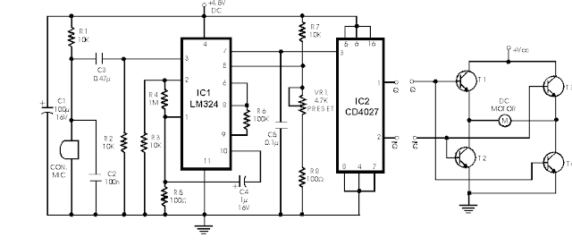
Sound Controlled Filp Flop

Described here is a very inexpensive solution to many phono-controlled applications like remote switching on, for instance, or activating a camera, tape recorder, burglar alarms, toys, etc. The circuit given here employs a condenser microphone as the pick-up. A two-stage amplifier built around a quad op-amp IC LM324 offers a good gain to enable sound pick-up upto four metres. The third op-amp is configured as a level detector whose non-inverting terminal is fed with the amplified and filtered signal available at the output of the second op-amp. The inverting input of the third op-amp is given a reference voltage from a potential divider...

Ultrasonic pest repellent

It is well know that pests like rats, mice etc are repelled by ultrasonic frequency in the range of 30 kHz to 50 kHz. Human beings cant hear these high-frequency sounds. Unfortunately, all pests do not react at the same ultrasonic frequency. While some pests get repelled at 35 kHz, some others get repelled at 38 to 40 kHz. Thus to increase the effectiveness, frequency of ultrasonic oscillator has to be continuously varied between certain limits....

Audio Visual Indicator for Telephones

Many a times one needs an extra telephone ringer in an ad joining room to know if there is an incoming call. For example, if the telephone is installed in the drawing room you may need an extra ringer in the bedroom. All that needs to be done is to connect the given circuit in parallel with the existing telephone lines using twin flexible wires. This circuit does not require any external power source for its operation. The section ...

the CD-ROM drive as a audio CD player without the computer

Most of the CDROMS available have an Audio-Out Output to either plug in the headphones or connect it to an amplifier. This circuit enables one to use the CDROM as a stand alone Audio CD player without the computer. This circuit is nothing but a power supply which supplies +5v, +12V and Ground to the CDROM drive and hence  can be used without the computer. You should buy a D-type power connecter to connect this circuit's outputs to the CDROM. The details of the D connector are shown along with ...

Infrared Head Phones

Using this low-cost project one can reproduce audio from TV without disturbing others. It does not use any wire connection between TV and headphones. In place of a pair of wires, it uses invisible infrared light to transmit audio signals from TV to headphones. Without using any lens, a range of up to 6 metres is possible. Range can be extended by using lenses and reflectors with IR sensors comprising transmitters and receivers. IR transmitter...

intercom using transistors

The circuit comprises a 3-stage resistor-capacitor coupled amplifier. When ring button S2 is pressed, the amplifier circuit formed around transistors T1 and T2 gets converted into an asymmetrical astable multivib-rator generating ring signals. These ring signals are amplified by transistor T3 to drive the speaker of earpiece. Current consumption of this intercom is 10 to 15 mA only. Thus a 9-volt PP3 battery would have a long life, when used in...

Stereo Channel Selector

The add-on circuit presented here is useful for stereo systems. This circuit has provision for connecting stereo outputs from four different sources/channels as inputs and only one of them is selected/connected to the output at any one time. When power supply is turned on, channel A (AR and AL) is selected. If no audio is present in channel A, the circuit waits for some time and then selects the next channel (channel B). This search operation continues until it detects audio signal in one of the channels. The inter-channel wait or delay time can be adjusted with the help of preset VR1. If still longer time is needed, one may replace ...

Pot plant water tester

This simple device checks if their is water in a pot plant. You stick the two probes(paperclips)into the pot plant and if the LED lights, it means there is water in the pot plant. You need to adjust the 47k potentiometer to set the level at which the LED goes ...

Programmable Digital Code Lock

A programmable code lock can be used for numerous applications in which access to an article/gadget is to be restricted to a limited number of persons. Here is yet another circuit of a code lock employing mainly the CMOS ICs and thumbwheel switches (TWS) besides a few other components. It is rugged and capable of operation on voltages ranging between 6 and 15 volts. The supply current drain of CMOS ICs being quite low, the circuit may be operated even on battery.  The circuit uses two types of thumbwheel switches. switch numbers TWS1 through TWS8 are decimal-to-BCD converter type while switch numbers TWS9 through TWS16 are 10-input...

Ultrasonic Pest Repeller

It is well know that pests like rats, mice etc are repelled by ultrasonic frequency in the range of 30 kHz to 50 kHz. Human beings can�t hear these high-frequency sounds. Unfortunately, all pests do not react at the same ultrasonic frequency. While some pests get repelled at 35 kHz, some others get repelled at 38 to 40 kHz. Thus to increase the effectiveness, freque- ncy of ultrasonic oscillator has to be continuously varied between certain limits. By using this circuit design, frequency of emission of ultrasonic sound is continuously varied step-by-step automatically. Here five steps of variation are used but the same can be extended...

Simple IF Signal Generator

Here is a versatile circuit of IF signal generator which may be of interest to radio hobbyists and professionals alike.Transistors T1 and T2 form an astable multivibrator oscillating in the audio frequency range of 1 to 2 kHz. RF oscillator is built around transistor T3. Here again a 455kHz ceramic filter/resonator is employed for obtaining stable IF. The AF from multivibrator is coupled from collector of transistor T2 to emitter of transistor T3 through capacitor C3. The tank circuit at collector of transistor T3 is formed using medium wave oscillator coil of transistor radio, a fixed 100pF capacitor C5 and half section of a gang capacitor...
Page 1 of 6912345Next

 
Design by Free WordPress Themes | Bloggerized by Lasantha - Premium Blogger Themes | cheap international calls